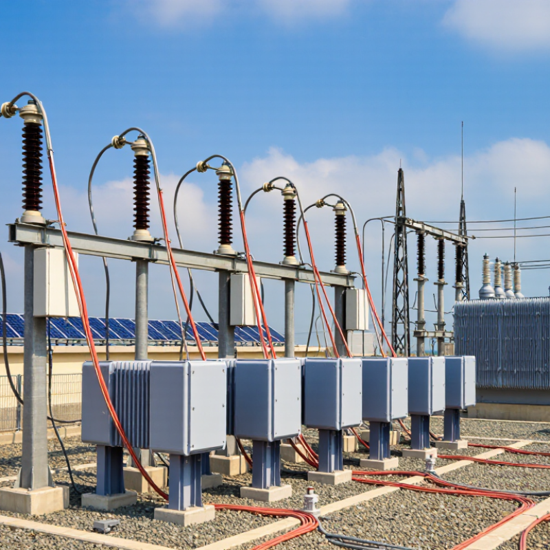
How to Choose a Lightning Arrester in 2026?

Choosing the right Lightning Arrester in 2026 is not a matter of selecting the highest voltage rating. It requires a clear understanding of the electrical system, installation environment, and expected surge conditions. A reliable choice begins with the system’s maximum continuous operating voltage, grounding method, temporary overvoltage exposure, and insulation coordination requirements. Small errors here can cause repeated failures, even when the arrester appears properly installed.

Field experience shows how quickly conditions can change. A dusty substation beside a coastal road may face salt pollution, moisture, and frequent switching surges. A rooftop photovoltaic system may experience different risks from a medium-voltage transformer in an industrial plant. The Lightning Arrester must also match the available short-circuit current and expected lightning discharge current. Housing material, creepage distance, thermal stability, and pressure-relief performance deserve careful attention. Installation length matters too. Long connecting leads can increase residual voltage during a fast surge.

Current technical guidance, including applicable IEC and IEEE practices, can support the evaluation, but standards should be checked for their latest editions and regional requirements. Manufacturer test reports, routine inspection records, and verified application data add practical confidence. Marketing claims alone are not enough. Sometimes, engineers focus heavily on nominal discharge current and overlook temporary overvoltage behavior. That is a weakness worth challenging. This guide examines the main selection factors, compares common arrester designs, and highlights mistakes that can reduce protection performance. The goal is not a perfect formula. It is a defensible decision based on measured conditions, professional judgment, and documented evidence.

How to Choose a Lightning Arrester in 2026?

What a Lightning Arrester Is and How It Protects Electrical Systems

How to Choose a Lightning Arrester in 2026?

A lightning arrester protects electrical systems from sudden overvoltage. It connects between a conductor and ground, then limits dangerous voltage during lightning or switching events. Under normal conditions, it remains nearly inactive. When a surge arrives, its metal-oxide elements conduct excess energy safely toward earth.

The arrester does not stop lightning. It controls the surge’s path and reduces stress on transformers, cables, control panels, and sensitive electronics. Proper grounding is essential. A poorly bonded grounding conductor can create dangerous voltage differences, even when the arrester itself is correctly rated. Keep connections short, straight, and mechanically secure.

Choosing an arrester requires more than checking voltage. Review the system’s continuous operating voltage, temporary overvoltage, discharge current, energy capability, and installation location. Medium-voltage equipment may need different performance levels than rooftop solar equipment or industrial controls. Check applicable technical standards, coordination requirements, and the manufacturer’s tested data. Field inspections should also examine aging, contamination, loose terminals, and moisture entry.

No arrester lasts forever.

A common mistake is selecting the highest-rated device without checking protection levels. That choice can leave equipment exposed. Another assumption deserves review: a surge protective device cannot correct weak earthing or poor cable routing. In practice, protection works as a coordinated system, not as one isolated component. A qualified engineer should verify the design before installation, especially where service continuity and human safety matter.

Identify Voltage, System, and Lightning Exposure Requirements

Choosing a lightning arrester in 2026 starts with voltage, not product size. Record the system’s nominal voltage, highest operating voltage, grounding method, and temporary overvoltage duration. Then select continuous operating voltage above expected phase-to-earth stress. IEC 60099-4 and IEEE C62.11 stress energy handling, residual voltage, and current capability. A field survey matters. Cable length, transformer distance, and parallel feeders can change surge behavior. A neat rule can still mislead.

System structure is equally important. A solidly grounded network differs from an isolated or resistance-grounded system. Check phase-to-earth and phase-to-phase protection needs. Coordinate the arrester with insulation levels and upstream protective devices. In industrial sites, motor starts and switching events may create repeated stress. The National Electrical Manufacturers Association identifies switching surges as a major consideration in surge protection design. Do not treat lightning as the only threat.

Exposure decides the arrester’s endurance. NASA Earth Observatory estimates roughly 1.4 billion lightning flashes occur worldwide each year. NOAA’s National Severe Storms Laboratory reports lightning channels can reach about 30,000 kelvins. Tall structures, open terrain, overhead lines, and high-ground locations deserve stronger risk assessment. Tips: map nearby strikes, inspect grounding resistance, and review failed arresters after storms. Use local lightning data where available. Shortcuts fail sometimes. Recheck the assumptions.

Compare Arrester Types, Ratings, and Protective Performance

How to Choose a Lightning Arrester in 2026?

Choosing a lightning arrester in 2026 means comparing more than a voltage label. For medium-voltage networks, metal-oxide, gapless arresters usually offer fast response and stable protection. Gapped designs may tolerate certain temporary overvoltage conditions, but they require closer coordination. Station-class units handle greater energy than distribution-class units. Check continuous operating voltage, rated voltage, nominal discharge current, and energy capability against the actual system. Do not confuse a higher rating with better protection. Residual voltage matters. Lower residual voltage generally leaves more insulation margin, provided the arrester survives expected lightning and switching energy. IEC 60099-4 test data can support a defensible comparison.

Tips: Measure the lead lengths, not just the arrester rating. Long phase and ground connections can increase voltage at the protected equipment. Confirm grounding resistance, system fault duration, insulation level, and local surge exposure. A compact installation drawing often reveals problems hidden in a spreadsheet.

Protective performance also depends on repeated surge duty. Review thermal stability, pressure-relief behavior, housing condition, and pollution resistance for the installation site. Coastal salt, industrial dust, and altitude may change the selection. A practical choice is rarely perfect on the first pass. Recheck assumptions with measured system data and manufacturer test certificates. In field reviews, the weakest detail is sometimes simple: an arrester is rated correctly, but installed too far from the transformer.

How to Choose a Lightning Arrester in 2026? – Compare Arrester Types, Ratings, and Protective Performance

Technical comparison based on commonly used IEC 60099-4 and IEEE C62.11 selection principles

Arrester Type Typical Construction Typical Application Common Nominal Discharge Current Voltage Rating Selection Protective Performance Energy and Temporary Overvoltage Capability Main Advantages Important Limitations Recommended Selection Priority
Gapped Silicon-Carbide Arrester Silicon-carbide non-linear resistor blocks connected in series with internal spark gaps. Legacy medium-voltage and older substation installations where replacement compatibility is required. Commonly 5 kA or 10 kA, depending on the design and applicable standard. Selected by system maximum voltage, grounding method, and the arrester's rated voltage. The gap must withstand normal system voltage without continuous conduction. Generally lower and less consistent than modern gapless metal-oxide designs because the spark-gap voltage contribution varies with current and front-of-wave steepness. Performance depends strongly on gap design, discharge history, and power-frequency follow current. Temporary overvoltage capability must be checked from the specific test curve. Suitable for like-for-like maintenance in legacy systems; no continuous leakage current through the resistor blocks during normal operation. Larger physical size, possible follow current, aging of gaps, and less predictable fast-front protective performance. Use primarily for retrofit compatibility. For new installations, compare against gapless metal-oxide technology.
Gapless Metal-Oxide Distribution Arrester Zinc-oxide metal-oxide varistor blocks without series spark gaps, normally enclosed in polymer or porcelain housing. Distribution transformers, overhead distribution lines, switchgear, motors, generators, and medium-voltage equipment. Frequently 5 kA or 10 kA for distribution applications; higher values may be specified for severe exposure. The continuous operating voltage, Uc or MCOV, must be suitable for the highest continuous phase-to-ground voltage. Rated voltage, Ur, is normally higher than Uc and must also accommodate temporary overvoltage. Good clamping performance and fast response. Residual voltage is normally specified at defined 8/20 microsecond current values rather than as one universal number. Good energy absorption for ordinary distribution duties, but the arrester must be coordinated with fault current, line discharge class, and expected lightning exposure. Compact, fast responding, no power-frequency follow current, and widely available in medium-voltage configurations. Excessive continuous voltage, repeated temporary overvoltage, moisture ingress, or inadequate thermal protection can cause premature failure. Confirm Uc/MCOV first, then compare residual voltage, energy capability, housing insulation, and disconnector behavior.
Gapless Metal-Oxide Station-Class Arrester High-energy zinc-oxide blocks with a mechanically robust housing and carefully controlled thermal and pressure-relief design. High-voltage substations, transformer terminals, busbars, cable terminations, generator step-up transformers, and critical transmission equipment. Commonly 10 kA or 20 kA for station and transmission duties; the specified class depends on the system and exposure. Uc/MCOV is selected from the maximum continuous phase-to-ground voltage. Ur must be coordinated with temporary overvoltage duration, grounding conditions, and insulation coordination studies. Very good protective performance when selected with a low residual-voltage ratio and installed with short, low-inductance connections. Protection level must remain below the equipment insulation withstand level with a suitable margin. High energy capability and improved thermal stability compared with basic distribution designs. Switching-surge energy may govern the selection on transmission systems. High reliability, strong energy handling, low protection levels, and suitability for expensive power-system assets. Higher cost and greater sensitivity to incorrect voltage selection. It may be unnecessarily large for ordinary low-exposure distribution points. Select by insulation-coordination study, switching and lightning energy, short-circuit requirements, and equipment criticality.
Line-Discharge-Class Arrester Gapless metal-oxide arrester categorized by its ability to withstand line-discharge energy associated with long overhead lines and cable systems. Transmission-line entrances, cable-to-overhead transitions, long cable circuits, and substations exposed to significant switching energy. Often 10 kA or 20 kA, with the required line-discharge class determined by system voltage and network configuration. Uc/MCOV must satisfy continuous voltage and temporary overvoltage conditions; Ur alone is not sufficient for final selection. Strong performance against both lightning impulses and switching surges when the line-discharge class and residual-voltage characteristics are correctly matched. Designed for repeated or high-energy discharge duty. Energy rating should be verified using the applicable line-discharge test class and system study. Appropriate for high-energy transmission environments and long-line switching events. May be oversized for short, lightly exposed circuits. Incorrect installation distance can still produce excessive voltage at the protected equipment. Use when line length, cable capacitance, switching operations, or network studies indicate substantial discharge energy.
Polymer-Housed Arrester Metal-oxide arrester blocks enclosed in a silicone-rubber or other polymeric weather housing, usually with a pressure-relief and disconnector system. Outdoor distribution and substation installations, polluted environments, compact switchgear, and locations requiring low weight and high contamination performance. Commonly 5 kA, 10 kA, or 20 kA, depending on the internal arrester design and application class. Uc/MCOV, Ur, phase-to-ground voltage, temporary overvoltage, and external insulation level must all be checked. Housing creepage distance must suit the pollution severity. Electrical protection is determined by the internal metal-oxide blocks; polymer housing improves outdoor insulation behavior and reduces the risk of dangerous fragmentation. Energy capability varies by internal design and is not determined by the housing material alone. Verify thermal stability, pressure relief, and energy-test data. Lightweight, hydrophobic surface, good pollution performance, reduced breakage hazard, and easier handling. Housing aging, seal degradation, ultraviolet exposure, and mechanical damage must be considered in harsh environments. Prefer for many outdoor applications after confirming creepage distance, mechanical loads, sealing, and arrester energy class.
Porcelain-Housed Arrester Metal-oxide arrester blocks enclosed in glazed porcelain with conventional external insulation and pressure-relief arrangements. Outdoor substations and installations where established mechanical and insulation practices favor porcelain housings. Commonly 10 kA or 20 kA for station and transmission applications; lower ratings are also used in distribution systems. Select Uc/MCOV and Ur according to system voltage, grounding, temporary overvoltage, and insulation coordination requirements. Can provide the same electrical protection level as an equivalent metal-oxide design when the internal blocks and test ratings are comparable. Energy capability is determined by the arrester block design, thermal stability, and pressure-relief performance, not by porcelain alone. Long-established technology, high mechanical strength, and predictable external insulation dimensions. Heavier and more brittle than polymer housing; broken porcelain can create hazardous fragments during severe failure. Consider where existing substation standards, mechanical loads, or lifecycle practices specifically favor porcelain.
Low-Voltage Type 1+2 Surge Protective Device Low-voltage surge protective device combining high-current impulse capability with protection against induced and switching surges, typically using spark-gap and/or metal-oxide technology. Main distribution boards, service entrances with an external lightning protection system or high lightning exposure, and industrial low-voltage installations. Impulse current Iimp is commonly specified for Type 1 duty; nominal discharge current In is commonly specified for Type 2 duty. Values must be selected for the installation risk and system arrangement. Select the maximum continuous operating voltage, Uc, above the applicable system voltage and verify the voltage protection level, Up, is below the withstand level of connected equipment. Good coordinated protection when installed at the service entrance with short conductors and correctly selected backup overcurrent protection. Must withstand the expected lightning current share, prospective short-circuit current, and temporary overvoltage specified by the low-voltage installation design. Protects complete low-voltage systems and can coordinate with downstream Type 2 and Type 3 devices. Incorrect lead length, poor bonding, wrong system configuration, or inadequate backup protection can severely reduce effectiveness. Verify system earthing arrangement, Uc, Iimp/In, Up, short-circuit rating, backup protection, and coordination with downstream SPDs.

Selection note: Uc or MCOV is the continuous operating-voltage limit, while Ur is the arrester rated voltage and does not replace a temporary-overvoltage study. Residual voltage, energy capability, line-discharge class, insulation coordination, grounding method, pollution level, short-circuit rating, installation lead length, and protective-device coordination should be verified from the applicable test reports and project requirements. Numerical current classes and performance values vary by voltage level, construction, and standard; the table therefore uses commonly encountered rating ranges rather than brand-specific data.

Evaluate Installation Conditions, Standards, and Maintenance Needs

Choosing a lightning arrester in 2026 requires more than matching voltage ratings. Start with the installation conditions. At a rooftop distribution board, record system voltage, grounding method, exposure, and available fault current. Short notes matter.

A qualified engineer should verify continuous operating voltage and temporary overvoltage tolerance. An incorrect value can cause premature failure. For exposed lines, check lead length and routing. Keep connections short, straight, and firmly bonded to the grounding network. Sharp bends increase inductive voltage during a surge. They do. IEC 61643-11 provides guidance for low-voltage surge protective devices. For medium-voltage metal-oxide arresters, IEC 60099-4 may apply. Local electrical codes can add requirements for spacing, enclosures, and disconnection. Confirm the current edition before approval. Documentation is evidence, not decoration.

Maintenance planning should match the environment. Inspect status indicators, terminals, seals, and grounding connections after severe storms, construction, or repeated outages. Coastal air and industrial dust need closer inspection intervals. Keep records. Define who isolates the circuit and how voltage absence is confirmed. A replacement plan is often missed. Some assumptions fail in the field. Review them after the first inspection. A catalogue headline cannot replace insulation coordination, test records, and a site-specific risk assessment.

Verify the Right Lightning Arrester for 2026 Applications

The right lightning arrester for 2026 must match the application, not merely its advertised discharge current. The IEA’s Renewables 2024 report forecasts almost 5,500 GW of new renewable capacity by 2030. More solar plants, battery systems, and connected substations will increase exposure to switching and lightning surges. Verify the system’s maximum continuous operating voltage, rated voltage, frequency, and temporary overvoltage withstand. Then check the protective level against the insulation coordination study.

Use IEC 60099-4 or IEEE C62.11 as the technical reference. These standards address metal-oxide arrester design, testing, and performance verification. Select the nominal discharge current and energy capability from the actual network duty.

A rooftop photovoltaic installation may need different coordination from a transmission substation. Review altitude, pollution, humidity, grounding resistance, and available short-circuit current. Small details matter.

The Uptime Institute Global Data Center Survey 2024 reported that 54% of significant outages cost more than 100,000 dollars. That figure is not a lightning-specific statistic, but it shows why protection verification deserves serious attention. A higher kA rating does not automatically provide better protection. It can create false confidence. Confirm residual voltage, thermal stability, enclosure protection, and cable length during installation. Ask for independent test evidence, not only a datasheet. In practice, the weakest grounding connection may defeat an otherwise suitable arrester. Recheck coordination after equipment changes.

Kontaktbox-Frau

  • CNC-STEP – Quick contact