

What Is a CNC Engraving Machine and How Does It Work?
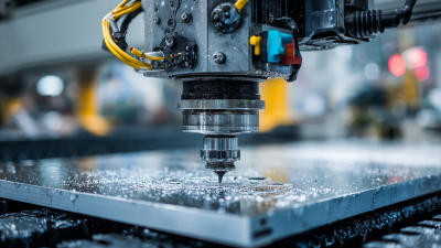
A cnc engraving machine converts a digital design into controlled movement, cutting or marking material with a rotating tool. The operator prepares a drawing, selects a cutter, and sets the workpiece firmly on the table. Software translates the design into instructions for the machine’s axes and spindle. As the tool follows those instructions, it removes material in measured passes. The result might be lettering on an aluminum plate, a shallow pattern in wood, or a precise mark on plastic. Small details matter. A loose clamp or unsuitable feed rate can spoil an otherwise accurate job.
Industry figures offer useful context, but they need careful interpretation. Grand View Research estimated the global CNC machine market at USD 83.99 billion in 2023, with projected growth through 2030. That report covers CNC machines broadly, not engraving equipment alone. It signals wider adoption of computer-controlled manufacturing, rather than proving demand for every engraving application. That distinction matters.
This guide explains what a cnc engraving machine is, how its main components work together, and what happens between a design file and a finished surface. It also looks at materials, tooling, setup, and common sources of error. The process is not entirely automatic. Operators still make choices about depth, speed, and tool condition, and those choices affect the result. Understanding the machine’s limits is part of using it well.
What Defines a CNC Engraving Machine: 3-Axis Motion, Spindle, and Controller
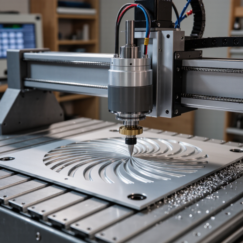
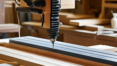
A CNC engraving machine is defined by three coordinated elements: three-axis motion, a spindle, and a controller. The X-axis moves left and right. The Y-axis travels front to back. The Z-axis controls cutting depth. Together, these movements guide the tool across wood, plastic, metal, or coated panels.
The spindle rotates the engraving cutter at controlled speed. Cutter diameter, material hardness, and feed rate determine surface quality. A small cutter can create fine lettering, but it needs careful depth control.
The controller converts digital toolpaths into motor commands. It also manages acceleration, position, and spindle signals. In daily workshop use, correct zeroing matters as much as machine power. A misplaced origin can ruin an otherwise accurate job.
The broader CNC machine market was valued at approximately USD 83.2 billion in 2023, according to Grand View Research’s CNC Machine Market Size report. That figure includes milling, turning, and other CNC equipment, not engraving machines alone. It still reflects growing investment in programmable production.
The cut is rarely perfect on the first pass. Material movement, dust, and tool wear can change results. Operators often refine speeds and depths through testing, which is less elegant than advertised but more reliable. Safety depends on guarding, secure workholding, ventilation, and trained operation.
How CAD/CAM Converts Artwork into ISO 6983 G-Code Toolpaths
A CNC engraving machine removes material with a computer-controlled cutting tool. Its accuracy begins long before the spindle starts. CAD software defines the artwork as lines, curves, text, or closed shapes. These digital details describe what the finished engraving should look like.
CAM software then turns that design into toolpaths. The operator selects a cutter, cutting depth, feed rate, and spindle speed. The software calculates safe movements around each feature. It then uses a post-processor to create ISO 6983 G-code. This code contains commands for coordinates, motion, speed, and tool control. The machine controller reads these commands and moves each axis accordingly. A simulation can reveal collisions, missed areas, or excessive cutting depth.
Small errors matter. A wrong origin can shift the entire design. I have also found that a clean preview may hide rough edges caused by poor tool settings. The material changes everything, too. Wood, plastic, and metal often require different feeds and depths. Some results need manual adjustment after the first test cut.
Tips: Set the work zero carefully and confirm the Z-height. Use a scrap piece before cutting valuable material. Inspect the G-code preview, not only the artwork. Keep toolpaths simple when detail does not require complexity. A slower test can prevent an expensive mistake.
| Stage | Data or Input | What Happens | Output or Check |
|---|---|---|---|
| 1. Artwork preparation | Vector geometry, text, or a raster image; material dimensions; intended engraving depth | The design is scaled and positioned within the work area. Vector artwork is typically made from paths; raster artwork may need tracing or conversion into scan lines. | A clean, correctly sized design with suitable closed contours or engraving paths |
| 2. CAD geometry | Lines, arcs, curves, text outlines, and the workpiece origin | CAD defines the geometry and its position. The operator sets a coordinate origin, often at a workpiece corner or its center. | Design coordinates in the selected units, such as millimetres or inches |
| 3. CAM setup | Tool type and diameter, spindle settings, feed rate, cut depth, and machine limits | CAM assigns machining operations to the geometry. Tool diameter affects path placement; depth and pass settings determine how the tool reaches the target depth. | Operation settings that suit the tool, material, and machine |
| 4. Toolpath generation | CAM operations, such as engraving along a line, tracing a contour, or filling an area | CAM calculates tool-centre motion, cutting moves, linking moves, and any programmed depth changes. | Ordered XYZ movement paths, with feed and spindle instructions where configured |
| 5. Post-processing | Calculated toolpaths and a post-processor configured for the target controller | The post-processor converts CAM motion into controller-readable NC instructions. ISO 6983 defines a format for numerical-control program data, but supported codes and machine behaviour can vary by controller. | An NC program commonly called G-code, checked against the machine’s supported dialect |
| 6. Typical program words | Modal codes, motion commands, coordinates, feed values, and auxiliary commands | Common examples include G21 for metric units, G90 for absolute positioning, G0 for rapid motion, and G1 for feed-controlled linear motion. Their availability and exact behaviour should be verified for the controller. |
Readable instructions such as G1 X25.0 Y10.0 F300; values and supported syntax depend on the job and controller |
| 7. Simulation and verification | Toolpaths, stock model, tool dimensions, work offset, and machine travel limits | Simulation helps reveal unexpected moves, missed geometry, excessive depth, or possible travel-limit issues. A dry run can verify setup before cutting. | Reviewed tool motion, safe clearances, and confirmed workpiece origin and units |
| 8. Machine execution | Verified program, secured workpiece, installed tool, and established work offset | The controller interprets the program and commands the machine axes and spindle. The cutting tool removes material as it follows the programmed path. | Engraved text, outlines, or filled regions on the workpiece |
| Machine function | Typically a spindle or engraving head, controlled axes, workholding, and a controller | A CNC engraving machine uses programmed movement to position a rotating cutter or another compatible engraving tool relative to the material. Machine configuration and capabilities vary. | Repeatable, computer-controlled engraving within the machine’s working envelope |
How Feed Rate, Spindle RPM, and Engraving Depth Control Cutting
What Is a CNC Engraving Machine and How Does It Work?
A CNC engraving machine uses computer-controlled motion to guide a cutting tool across wood, plastic, metal, or other materials. The spindle rotates the tool, while programmed movements create letters, lines, and detailed patterns. Cutting quality depends heavily on three settings: feed rate, spindle RPM, and engraving depth.
Feed rate controls how quickly the tool travels across the workpiece. A slow feed with high spindle RPM can create heat, rubbing, or melted edges. A fast feed may cause chatter, broken cutters, or rough corners.
Spindle RPM should match the tool diameter and material. Smaller cutters often need higher speed, but not unlimited speed. Engraving depth also matters. Shallow passes preserve fine details and reduce cutting pressure. Deep passes remove more material, but they can distort thin lines.
In practice, I usually test a small area first. A setting that worked yesterday may fail on a different sheet.
Tips: Secure the workpiece firmly and check tool sharpness before cutting. Begin with a conservative depth and increase it gradually. Listen for unusual vibration. A steady cutting sound is useful, but it is not perfect evidence. Measure the finished groove, inspect its edges, and adjust one setting at a time. Keep notes, even when the result looks disappointing. Small experiments often reveal more than confident guesses.
How Engraving Tools Work Across Metal, Plastic, Wood, and Composites
A CNC engraving machine removes material with a computer-controlled cutting tool. The spindle follows programmed paths, while speed, feed rate, and depth control the result. Unlike hand engraving, it repeats the same geometry with measured consistency. Small errors still matter.
Metal needs rigid fixturing, sharp carbide tooling, and controlled chip removal. Aluminum often accepts higher cutting speeds, but heat can smear the surface. Steel usually requires slower feeds and stronger tooling. Plastic behaves differently. Excessive heat may melt edges or leave a cloudy finish. Wood cuts easily, yet grain direction can pull the tool sideways. Composites are less predictable because abrasive fibers wear the cutter quickly. Dust extraction is essential.
According to Fortune Business Insights, the global CNC machine market was valued at about 83.8 billion dollars in 2022. This growth reflects wider use of automated cutting across industrial materials. However, market growth does not eliminate setup mistakes. In practice, a test pass on scrap material often prevents expensive rework. A 0.1-millimeter depth change can alter lettering clarity, especially on thin plastic. It is unforgiving. Toolpath simulation helps, but it cannot fully predict grain tear-out or composite delamination. I would also question relying on default settings; they are convenient, not universally correct. Surface finish, tool wear, and material batch differences deserve inspection after every significant production change.
How ISO 230-2 Measures CNC Axis Positioning Accuracy and Repeatability
What Is a CNC Engraving Machine and How Does It Work?
A CNC engraving machine converts digital G-code into controlled spindle movement. The cutting tool removes material along programmed X, Y, and Z paths. ISO 230-2 matters because smooth engraving does not prove accurate axis positioning.
Positioning accuracy describes how closely an axis reaches its commanded coordinate. Repeatability describes how consistently it returns there. In a common ISO 230-2 test, each target position is approached repeatedly from both directions. Engineers record deviations, reversal error, and dispersion across the travel range. Five repeated measurements can reveal a 0.01 mm return error that one test may hide. Small errors become visible in fine lettering.
Numbers need context. ISO 230-2:2014 defines measurement methods, not one universal acceptance limit for every engraving machine. Temperature, spindle vibration, backlash, tool deflection, and machine leveling can change results.
A cold morning can mislead.
NIST Technical Note 1297 recommends reporting measurement uncertainty, rather than presenting one number as absolute truth. With a coverage factor of k=2, expanded uncertainty commonly represents about 95% coverage under suitable statistical assumptions. A reliable inspection report should state the instrument, temperature, travel direction, sampling points, and uncertainty. The process is less glamorous than engraving. It is more honest.
Related Posts
-
Why Investing in CNC Machines Can Boost Your Production Efficiency by 30% Financially
-
Unlocking Creativity: How a CNC Wood Router Transforms Your Woodworking Projects
-

2025 Yearly Trends in Best Wood Carving Machinery You Should Know
-
Why Choose a CNC Wood Carving Machine?
-
Navigating Global Trade Standards for Best Desktop CNC Machine Import and Export
-
Top 5 CNC Wood Router Machines You Should Consider?

Siemensstraße 13-15
47608 Geldern
NRW Deutschland
Mail: sale@atmmachinesolutions.com
Head office:
+49 (0) 2831 91021-20
Fax:
+49 (0) 2831 91021-99
SUPPORT and INFO
from 3 p.m. to 6 p.m:
+49 (0) 2831 91021-60
( please ring for a long time )
Monday to Friday
8.00 – 12.30
and 13.00 – 15.00
Visit / collection by appointment only!
➣ Sign up for our newsletter
Benefit from a 20% discount, don’t miss any events and always stay up to date.
To access the actual content, click on the button below. Please note that data will be passed on to third-party providers.
More information