| The functions in the Operat. menu |
 |
The functions available in your program are dependent on your program configuration and can deviate from this description. Current information on the operation of the functions can always be obtained using the program help. |
 Before carrying out a function in this menu the paths (points, sections and contours) must be marked. the marking takes place using the Marking tool in the list of aids. Using the Marking toolyou can select the individual points, sections or contours in the current layer (ActLayer) through clicking-on or in a rectangle. Before carrying out a function in this menu the paths (points, sections and contours) must be marked. the marking takes place using the Marking tool in the list of aids. Using the Marking toolyou can select the individual points, sections or contours in the current layer (ActLayer) through clicking-on or in a rectangle.
To select an individual section the cursor cross must be led as close as possible to a line of the section to be sought and marked using . Several sections to be selected are framed using a rectangle. Sections must lie completely in the rectangle. For input, set the cursor on a corner of the rectangle, press the key , pull the rectangle diagonally over the section to be marked and then release the key.
Before a renewed selection the old markings are deleted. If several contours are to be marked one after another then press the key simultaneously with the marking . Another type of marking is available using mark TrackPosn and mark all. The selected paths are marked in red. With concurrent pressing of the key a path (section or contour) is sought in all layers. The layer with the nearest path is activated and is now the ActLayer and the path is marked. Here it is not possible to insert using or search in the rectangle.
In functions in which an input using the cursor takes place, depending on the number of vectors either the tracks themselves or with the exceeding of a limit, a rectangle is also drawn. Following the adoption of the tracks the rectangle is deleted and the tracks displayed.
Attention: The marking and the functions in the Operat Menu may not be applied on calculated milling data (with tool data), because then milling information and the logical coherency of the data are lost.
If paths are already marked then convert can be opened using or . Using the input the position, size, scaling, the rotation and slope angle of marked objects are altered. The input convert displays the horizontal and vertical coordinates of the object.
| Position, angle of rotation, scale/mirror, dimensions, slopes: |
Dialogue field for processing the object. |
| X, Y / An, X, Y / H, V: |
Relative/ABSOLUTE coordinates of the marking points set. |
| Relative/ABSOLUTE (for position, angle of rotation): |
Coordinate reference for position and angle of rotation. |
| Individual/proportional (for scale/mirror, dimensions): |
Individual: the figures are entered individually. Proportional: with modification of a figure, the second figure is altered appropriately. |
| Marking point: |
The marking points correspond to the eight holding points of a selection and the middle point of the object. The X/Y coordinates refer to these points. |
| Allocate duplicate/original: |
Creates a copy of the object at a new position or allocates the determined options to the marked object. |
The marked paths are displaced relatively or absolutely, freely in X/Y, horizontally only (x) or vertically (y) only. For the displacement at the cursor. If the input parameter Capture grid is set to a value > 0, then the basis point can be captured. With Capture grid = -1 capture with this is on support points of the marked sections and with Capture grid >= 0 on support points of the graphic layer defined using Capture layer .
| Duplicate |
A copy is made from the marked sections and contours and also carried with every cursor movement |
| Displace |
The marked sections and contours are displaced using the cursor. |
The functions of the duplicate/displace selection:
| Relative/absolute: |
A number input is assessed relatively (as displacement to the last position) or absolutely (reference to zero point). |
| Displace XY: |
Displace sections in XY. |
| Displace X: |
Displace sections horizontally only. |
| Displace Y: |
Displace sections vertically only. |
 |
 |
The marked tracks and sections are scaled. |
The functions of the height (dimensions) selection:
| Dimension %: |
Scaling using cursor or % input. |
| Dimension 2 Pt.X / Y: |
The marked data are converted according to a X (Y) reference dimension in the scale. For this, 2 X (Y) positions are entered using the cursor. The width (height) is displayed and can be replaced by a new value. Following confirmation of input the marked paths are converted in the scale relative to this input. Only the X and Y coordinates (2D) are converted . Possibly existing Z values remain unmodified. |
| Dimension limit X / Y: |
The marked data are scaled to a new overall width/overall height. |
| Distort X / Y: |
Distortion using cursor or % input. |
 |
The marked paths are sloped (inclined) retaining their original height. |
 |
 |
The marked tracks and sections are rotated. The paths can be freely rotated, directly 90° about their middle point (input +90 / -90) or following input of a basic point and the angle of rotation (input rotate).. |
| +90°/-90°: |
Rotate the marked paths by 90 deg. |
| Rotate: |
Rotate the marked paths freely using the cursor. |
| Rotate horizontally /rotate vertically: |
All paths are so rotated after the input of 2 reference points (input using the cursor), that the reference points lie on a horizontal or vertical line. For this input 2 positions using the cursor. |
 |
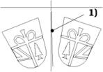
1) = mirror axis |
The marked paths are mirrored to an X/Y axis or to a freely input axis. |
| Left /centred / right / bottom / middle / top: |
The marked paths can be mirrored about the given axis. |
| Rotate+Mirror: |
The marked paths are mirrored about any desired axis. For this, after the input of the basis point of the mirror axis, the 2nd mirror axis is to be input.
If the input parameter Capture grid is set to the value > 0, then the basis point and the 2nd point of the mirror axis can be captured. With Capture layer = -1 capture with this is on support points of the marked sections and with Capture layer >= 0 on support points of the graphic layer defined using capture layer.
A copy of the marked sections is newly displayed with every change of the mirror axis. After pressing the key the tracks are frozen at the instantaneous position and the question Delete old object Y/N is to be answered. YES: the old marked sections are deleted. NO: the old marked sections are retained. |
The marked tracks and sections are centred in X/Y to a graphic object to be selected. With simultaneous pressing of the key capture centre to .. on the next object which is sought in all layers.
 |
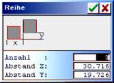
The marked paths are arranged in series. |
| Linear series linear:
|
 |
The marked sections can be copied several times. If copies in the horizontal and vertical direction are to be generated, then the function Tile is to be employed. |
| Number: |
Number of objects in the series. Number must be >1. (Input 2 .. 999) |
| Separation X/Y: |
Separation of the copies in X/Y direction. At least 1 separation in X or Y must be <> 0. |
Polar series:
The marked tracks sections are arranged several times in the circle. For this, first the middle point of the arrangement is to be entered or selected using the cursor. All data can be edited in the following input.
| Middle pointX/Y: |
Middle of the arrangement |
| Separation day: |
Separation of the centre of an object to the middle point. |
| Number: |
Number of the objects to be created. |
| Start angle: |
Start angle for the arrangement. |
| Angle to be filled: |
Area in which the objects are to be arranged. |
| Angle of rotation: |
Angular separations of the objects. |
| Rotate objects: |
| YES: |
The objects are rotated. |
| NO: |
The objects remain in their original position of rotation. |
|
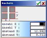
Tile:
 |
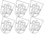 |
The marked paths are copied several times by columns and by lines. If series are created which do not run horizontally or vertically then the function Series is to be employed. |
The elongation of the graphic is always proposed by the program as separation. The function is cancelled if the number X = 1 and Y = 1 or both separation values = 0 are input.
| NumberX,Y: |
Number of the horizontal / vertical graphics (1 <= number <= 100) incl. the original graphic. |
| Separation X,Y: |
Horizontal / vertical copy separation in positive or negative direction. |
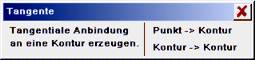 |
Create a tangential connection at a contour. Possible are tangents from one point on a contour or tangential connections between 2 contours. The contours must be closed and free of error. Tangents can be created on almost any desired contour or polygon. At the tangent contact the contour is interrupted. Limitation: the tangent start points may not lie in the contour. |
| Point -> Contour: |
Create a tangential connection starting from a point on a contour. |
| Contour -> Contour: |
Create a tangential connection between 2 contours. |
The marked paths cut each other and separated at the interfaces. After this the sections to be removed are marked and deleted. The vectors within a contour string do not cross each other.
If contours are demanded then the paths must be combined with each other after the cutting and editing (e.g. using Prepare . Combine tracks or Edit . Posn. combine).
 |
Procedure for example graphic:
1) Mark paths and cut.
2) Mark redundant sections and delete.
3) Using Prepare . Combine tracks create a section. |
The path to be trimmed is crossed with another path. Subsequently the overlying paths can be deleted.
Select paths.
Select one after the other the path to be trimmed and the path with which the trimming is to be done. Paths can be single vectors, sections and closed contours.
Select path to be trimmed! (Path1).
The path which is to be trimmed (path which is to be modified), is to be selected first. Trim with..(Path2): select path with which trimming is to be done (path remains unchanged).
Dependent on how the path to be trimmed (Path1) has been selected, various results are possible:
Marking in Path1.
Path1 is simply crossed with Path2.
Marking on first or last vector.
Path1 is crossed with Path2. If the extension of the first/last vector results in an interface with Path2, then the vector is extended.
Marking of a single vector.
The vector (Path1) is crossed with Path2. If the extension of the vector results in an interface with Path2, then the vector is extended in the corresponding direction.
| Merge (from eSIGN2D (v3)) |
For merging, 2 contour blocks must be selected one after the other, which are to be merged together or combined. A contour block can consist of one or more contours or combined contours. Open sections are allowed for stamping out only. The contour blocks are to be selected using the cursor. The respective selection is ended using or . The first contour block is marked green, the second blue.
 |
2 contours |
Merged with summation |
| Stamp out: |
The paths (contours and sections) in Block 1 are stamped out with the contours in Block 2. Stamping out allows 2D and 3D paths. Milling data can also be stamped out here. |
| Summation: |
The outer summation from both contour blocks is formed. This function is permitted for contours only. |
| Together: |
The inner summation from both contour blocks is formed. This function is permitted for contours only. |
| Difference1: |
Contour Block 1 is stamped out with Block 2 and combined as contours. This function is permitted with contours only. |
| Difference2: |
Contour Block 2 is stamped out with 1 and combined into contours. This function is permitted with contours only. |
| Section > contour (HCAM only) |
 |
The marked paths (tracks, sections) are converted into contours (double line) with the specified separation. The minimum vector length is 0.001mm, all shorter vectors (e.g. in rounding offs) are removed. |
| Contour width: |
Width (separation) of the double line. For contour widths > 0.01mm the settings in Input parameter . AutoCorr are used for the offset calculation. the contours are rounded off in the outer corners using Round-off angle 2D. |
 |
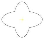
Track creation from overlapping sections and contours.
Margin top: 0; margin bottom: 0″>1) Specification: sections which overlap each other.
2) Result according to Section > Contour and 2D correction outwards. |
| Displace contour (from eSIGN2D (v3)) |
 |
 |
Calculate parallel contour(s) to the marked contour(s). |
| Offset [mm]: |
Calculation offset in mm. |
| Inwards/outwards: |
| Inwards: |
Correction inwards. |
| Outwards: |
Correction outwards. |
|
| Round/pointed: |
| Round: |
Round-off corners. |
| Pointed: |
Corners sharp-edged. |
|
| Retain/ delete original: |
| Retain |
After calculation original and offset tracks are present. |
| Delete: |
After calculation only offset tracks are still present. |
|
| Calculate: |
Start the offset calculation. |
| Displace line (from eSIGN2D (v3)) |
 |
 |
Calculate parallel path to the marked lines/sections. Contours can be better calculated using Displace contour. |
| Offset [mm]: |
Calculation offset in mm. |
| Right / left: |
Correction direction right/left of the section run direction. |
| Retain/ delete original: |
| Retain: |
After calculation original and calculated paths are present. |
| Delete: |
After calculation only calculated paths are present. |
|
| Calculate: |
Start the offset calculation. |
Import vector data (LG1, H2R) as macro. After import, the macros are marked and can be placed immediately or matched with the functions in the menu Operat. So long as a marking is not removed for imported macros the reference points in the functions duplicate and displace are already known and must not be implicitly input.
The marked paths are saved in a macro file together with a reference point. Macros are always reoccurring graphics (2D = H2R or 3D = LG1), which are input once and saved in a library. They can then be easily loaded and matched using Operat . Import macro.
 |
 |
For reference point input with Input parameter . Cursor capture grid > 0 and the setting Capture layer (draw): = -1 : on the marked point, 0..: capture on the point in the respective layer. |
| Ref. grid: |
Select one of the 9 main reference points. |
| Ref. free: |
Freely input one reference point. |
| Save: |
Save the macro with reference point in a file. |
Polylines are required for surface relief runs, projections etc. They may have no re-entrant angle. Frames are employed as work limits for automatic clearances (in CAM . MillTr2D and in Auto correction), if Layout . Frame is switched to YES. A frame must consist of closed contours and may have no overlapping (not even with milling corrected paths). The frame must be suitable for hatching or milling correction. |