

Relief design using ReliefVTR
2D to 3D Relief converter / Line to 3D
Relief design ReliefVTR.
Design on background graphic
Relief creation
Relief resolution
Relief design
Work steps for Relief design
Create Relief objects
Relief combination (Logic)
The mirror run
The ReliefVTR menu
Slants 3/4Pt
Mirror
Border + plan
Ellipse
Section / cylinder
Polyradius
Pattern
Insert Relief
LINE-Grav Param
LINE-Grav Input
Scale/smooth
Edit object
Object search
Object sequence
Object clr
Copy object
Exchange object
Relief position
Relief height line
Show Level
Dimension line
Norm / zoom projection
Render
New Relief
Recreate
Relief design ReliefVTR.
Reliefs are calculated in ReliefVTR from 2D line graphics. The work sequence for finished milling data, as a rule, consists of the following steps:
| 1 | 2D path creation (Line design) in the CAD. |
| 2 | Conversions of paths into spatial relief data in ReliefVTR. |
| 3 | Calculation of milling paths from the created relief. |
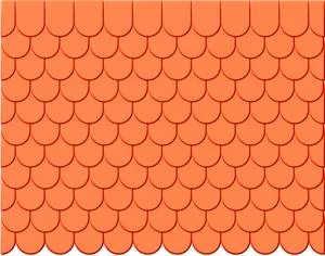
If a specified graphic (photo) is to be revised, then it can be worked in the background in the CAD and the necessary line graphic drawn over this. Colour and b/w photos are best save in a .jpg file and loaded in the CAD using the aid Graph background . Load backgr-image. When saving, take note of the correct dimensions (measurements) of the photos. jpg images are loaded in the background with the saved measurements.
In the CAD draw your contours and sections over this photo. Best detected on the background are graphics with the light layer colours (Layer#6..10). In suitable images contours can also be sought using Edit Relief . Layer border. The lines and contours created should sensibly already be shared out to layers. The Layer #15 is reserved as storage for ReliefVTR and my not be used in the CAD.You can generate a 3D shape from the paths in the CAD using ReliefVTR. For further drawings an editing in the CAD you can choose between Backgr-image and Relief as background.
Note: The border search in photos using Edit Relief . Layer border is frequently difficult, because photos are usually spotty. Improvement can be achieved by smoothing the images using Edit relief . filter. Here you should attempt the smoothing using the functions Error pixel, Outlier andapproximate. As far as no experience is available, the functions can be applied one after another in the listed order.
For relief creation in ReliefVTR first an empty relief is created using New relief. Here you should leave the proposed settings for the draft phase unchanged. With this, a coarse image is created, which can be edited quicker. Only with the final relief creation do you set the relief resolution to the desired size. For very deep reliefs please also observe the relief Z range (depth (Z)). This is preset to 10mm and suffices for normal reliefs in medallions and jewellery range. If the relief with this setting exceeds range from +/- 32mm, then errors are to be expected. If deeper reliefs are planned, then the Z range should be set correspondingly greater. On the other hand with greater depths the Z resolution and thus the quality are reduced.
All reliefs for relief creation are assigned to the objects (paths). You can reselect, modify an object at any time and, using the adjusted object data, create a new relief very rapidly. Important for the creation of reliefs from 2D paths is a precise idea of the work sequence, because, with the relief creation, in addition to the 3D geometry the linkage logic (sequence) is important. If, for example, a coin/medal is to be created then first all tasks in the flat area are finished and finally the sphere for a convex surface is created.
For relief creation marked the desired contours in the CAD and with this change into the ReliefVTRmenu. If the same paths are required for several paths (e.g. mirror + inclined surfaces), the it is sensible to create a copy of the paths before the change to ReliefVTR. For this, copy your paths into an empty layer, mark the contours in this layer and change to ReliefVTR. Following the relief creation (allocation of the relief characteristics) these contours are adopted in the object list for the relief creation and are no longer available for the immediate CAD operations. Mark only the paths for a relief object. With too many paths one easily loses the overview. Also, not all selection possibilities of the CAD are available in ReliefVTR. If the paths are converted in the desired fashion, then change into the CAD , mark the next paths and go with these to ReliefVTR etc. Fundamentally it is not permitted to copy or edit data from Layer#15.
If the now created relief corresponds with your ideas and if all editing tasks are completed, then you can have the final relief created. For this set the resolution in new relief in the final dimensions (e.g. 0.02mm for coin relief; 0.1mm for wood work etc.) and have the relief calculated using new create. With high resolutions and large measurements this can, under certain conditions can take a long time. Because this procedure runs fully, this not so crucial.
You achieve favourable conditions if milling resolution (milling track separation) and relief resolution are in agreement with each other or if the relief resolution lies at 2-..4 times the milling resolution. You can save considerable calculation time if you avoid unnecessarily high relief resolution and match this to the milling resolution.
Points in grid format similar to the image data PCX, TIFF, BMP etc. are saved in relief. This format is very suitable for the creation of 3D image data for normal reliefs with high resolutions. For large tasks, limits can, however, also be exceeded rapidly which greatly reduces the working rate. Therefore reliefs with a scope of more than 10 million points should be avoided . The calculation and milling correction of a relief10 million points even with very quick computers still requires considerable computer time. The relief data amount is dependent on the X and Y measurement and the point separation. Thus, for example, for a relief of X = 50 mm and Y = 50 mm with a point separation of 0.05mm, 1million points are created. With a point separation of 0.02mm and same measurements these are already 6.25 million points. The data created for your relief (position, measurements and resolution) are displayed using Relief file . Status.
If fine structures are to be created, then the relief must be set naturally at the appropriate resolution. If, for example, a line with vertical flanks and with a width of 0.1mm is drawn, the relief must be created with a minimum resolution of 0.1mm, better however, with 0.05mm. If this line is also rounded-off then the resolution must be set once again higher. In a case of doubt check the achievable relief quality using a number of sample lines. On the other hand, relief resolutions smaller than 0.02mm are barely sensible because the realistically achievable tools are barely capable of dealing with this measurement.
Note: Due to the point separation a vertical flank (milling steepness) can never be achieved.
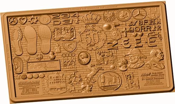
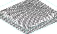
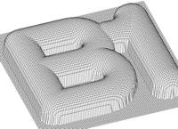
With ReliefVTR designed relief table
To work with ReliefVTR, for the best results use the icon menu for a rapid change of the program modules. The program module can be selected in the icon menu with a click from the CAD. From ReliefVTR you access the CAD also in the icon menu by clicking-on file, CAD or CAM.
In ReliefVTR a relief can be created, modified and combined from previously provided vector data though object allocation. Thus, for example, vector lettering and drawings as well as surfaces can be installed in relief. Individual areas can be raised, lowered or deleted through addition, subtraction etc. Surfaces can be filled planar at any desired level. For the borders a formable surface relief run an be employed. The functions in ReliefVTR are completely object-oriented. The individual objects can be edited freely at any time. or can put together a relief from sections and contours with allocated characteristics and from other reliefs (comp. Relief File . Export extract and Export frame). In addition to the complete creation of reliefs from vector data an existing relief can be modified, using the functions, for example through addition of surfaces, lettering etc.
Some of the functions in ReliefVTR use surface relief runs. These runs are referenced and not tied to the data. The surface relief runs are saved automatically in the PROJECT directory.
Objects with characteristics are saved in Layer#15. Although these paths could be worked in the CAD, created objects should not be modified directly in the CAD, because through this the characteristics are lost. If you wish to revise the paths of an object, then produce a copy using ReliefVTR . Copy, object, modify this and readopt the object in exchange object.
The ReliefVTR menu breaks down into the areas
- create objects (insert slopes .. relief),
- edit objects (edit object .. exchange object) and
- relief aspect (relief position .. render),
- adjust and create reliefs (new relief, newly create).
| 1 | Create vector data (paths) in the CAD (by scanning, engineering etc.). You can also scan-in a photo, import as relief, place in the background and draw over it. Please not that for some objects closed contours are demanded. |
| 2 | Mark the vector data and change into the ReliefVTR menu. The vector data are now displayed in blue-green. |
| 3 | Create an empty relief using New relief. For the draft phase leave the relief resolution (resolution [mm]) in the proposed size. |
| 4 | Select the desired object and according to requirement click-on the associated vector data. The vector data are now marked in red. Input and create objects completely. Thereafter the paths are marked in magenta. |
| 5 | As required edit objects. |
| 6 | Finally, for increased resolution, finally calculate the relief using New relief. |
Using the following functions and using simple means create relief objects from contours, sections, surfaces and reliefs. All objects can be linked with the background (the already existing relief) using logical operations (ADD, SUB, COPY, AND, OR). For this reason, under certain circumstances, it is important also to define the sequence clearly in addition to the geometry. The logical operations are explained under Relief linkage.
The object is linked logically to the already existing relief (background). Depending on the type of object some linkages are not available. The most important linkages are ADD (+), SUB (-), COPY and OR (max).
 |
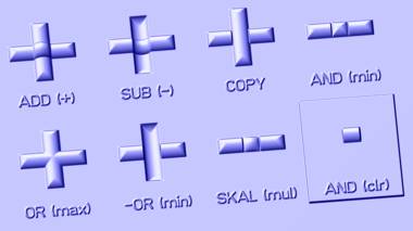
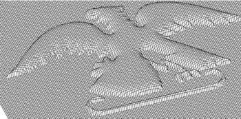
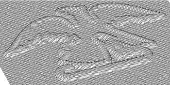
Emboss effects of the relief linkage (horizontal fields). Incised under background (horizontal fields). The examples for AND (clr) are always created separately. |

| ADD (+) | The new relief point is added to the background. |
| SUB (-) | The new relief point is subtracted from the background (incised). |
| COPY | The new relief point is set at the position of the background – the previous content is overwritten (replace). |
| AND (min) | The new relief point is linked with the background UND – i.e. the height, which is jointly held in both is placed (the smaller value is adopted). |
| OR (max) | The new relief point is linked to the background OR – i.e. the greatest value is adopted. The height is available in the background or in the object. |
| -OR (min) | Subtraction and/or linkage (incised OR). |
| SCALE (mult) | Multiply the background with the object (scale). |
| AND (Clr) | Stamp out the background with the object in 3D. |
| Inverse | The background within the object is inverted (mirrored in Z) (only in combination with border and plan without border). |
![]()
![]()
| Active/ Inactive | Create/do not create object. Using this function an object can be temporarily deactivated in the editing phase, i.e. with create relief this object is not taken into account for the relief calculation. |
![]()
![]()
Newly input objects, following their complete definition, are entered into the existing relief using create and are thereafter immediately visible. If existing objects are edited, then the settings can be fixed using adopt. If these modifications are to be visible, the after this the relief must be completely built up using Create new.
Some functions in ReliefVTR employ surface relief runs. The surface relief runs must be available as file. For this, the sections created here are saved (in the directory PROJECT ) before their first application. With the functions File . Project new/ open / save you have the possibility of ensuring a task completely with all associated data.
Polylines may possess no re-entrant angles. The polyline run for surfaces differs fundamentally from the run for sections. The surface run is always formed from the contour inwards and usually has an upward progression. The section run is projected to the right and left from the section, has its highest point usually in the middle and a falling progression. For the surface relief input the program automatically selects the correct input form. For the intersection selection the user must determine the correct run.
 |
 |
| Surface relief run for surfaces. | Surface relief run for sections. |
| Help for this input. | |
| Select a run from the data carrier. You should always be established in the PROJECT directory so that a task can be completely safeguarded. | |
| Save a run in a file. You should always establish sections in the PROJECTdirectory so that a task can be completely safeguarded. | |
| Adopt the inputs and create the mirror run. | |
| Abort the input and create no run. | |
| End height of the polyline [mm]: | Highest point of the polyline. |
| Start value [mm]: | Offset in horizontal direction. |
| Width of the polyline [mm]: | Total width of the polyline. |
| Start angle [°]: | Start angle of the polyline (0..90°). |
| End angle [°]: | End angle of the polyline (0..90°). |
| Intersect.select. | Selection of the regular intersections (straight, radius, …, see below). |
The intersection selection:
The above described interface input is suitable for most of the rather more artistic applications. Some rather more technical applications demand clearly defined runs (e.g. slants (diagonal) and radius), which can be input here.
Selection of the intersections available. |
Examples for diagonal, radius – and radius + with the created runs. |
Inputs for the polylines:
| Height of the polyline (z): | Height, elongation in Z direction. |
| Web width (a): | Width of an optional web (planar run at height of the polyline). |
| Start angle(ß): | Start angle should be specified >= 0 or a web width >= 0. |
| Checkpoint 1 (x,y): | 1st interpolation point for parabola and Bezier curve. |
| Checkpoint 2 (x,y): | 2nd interpolation point for Bezier curve. |
| Mirror Z: | Using YES the polyline is saved in Z (for surface runs). NO creates a intersection in the direction of the symbol (for sections). |
The areas limited by contours are converted into slant relief areas. The contours for which a relief surface is to be calculated must be selected using the cursor. The surface is determined by 3 points (P1, P2, P3) or by 4 points (P1 .. P4) in X, Y and Z. The points may not lie on a line and should enclose an as large as possible surface.
 |
Slanted slopes with 4Pt. |
The Z values (Z1, Z2, Z3(, Z4)) can be input directly manually or following , selected in the relief. With input of for the Z value the current value at the instant of the surface creation read from the relief. For the Z numerical value ‘?’ is displayed during the input. With this surfaces can be created independently one after the other. If the reference height is changed then all surfaces dependent on this are changed with new creation. |
| P1, P2, P3: | X/Y coordinates of the support points. | ||||
| Z1, Z2, Z3: | Z values of the support points. The Z values can be input directly manually or following , selected in Relief. With input of for the Z value the current value at the instant of the surface creation read from the relief. For the Z numerical value ‘?’ is displayed during the input. With this surfaces can be created independently one after the other. If the reference height is changed then all surfaces dependent on this are changed with new creation. | ||||
| Position: | Selectable are a = absolute and r = relative.
|
||||
| Slants 3Pt. / 4Pt.: | Switch for point/4 point input. |
Create a convex surface relief surface with the help of a run. The run is set in the input surface relief run and is loaded from a file. The contours for which a relief surface is to be calculated must be selected using the cursor.
 |
 |
| Run: | Shape of the run from the border to the surface middle. The run is set in the input Surface relief run. | ||||
| Basic height: | Height displacement in positive or negative direction. Alternative to the manual numerical input, the Z value can also following or be adopted in the numerical input from the existing relief. | ||||
| Interpol.: | Using interpolate > 1 a coarsened surface relief surface is created rapidly and thereafter interpolated. Interpolation = 1 creates a surface relief surface with the max. possible resolution. This type of surface creation can take a long time. The value for interpolation is incremented from von 1 .. 5 by clicking-on. Standard setting = 2. | ||||
| Smooth stage: | Additional smoothing function for the surface relief surface. With this, edge faults and formation of peaks can be suppressed. The value for smoothing level is incremented by clicking-on 0 .. 5. | ||||
| Method (Mirror..corner): | Influencing of the surface run. Adjustable are the methods mirror, spherical 1, .. 8 and corner. The settings spherical 4 .. spherical 6 produce round surface runs with little peak formation. The settings mirror and corner produce significant peak formations. |
||||
| Scaling Z: | Modify the surface relief surface in height (direction Z) using a factor. The setting 1 gives a surface relief surface in the height of the surface relief run. The input 0.1 .. <1 gives a flatter surface relief surface. The inputs >1 .. 10 give a raised more convex surface relief surface. | ||||
| Scaling X: | Modify the surface relief surface in width (in surface relief run direction X) using a factor. Scaling for the surface relief run. The setting 1 leaves the surface relief run unchanged. Settings 0.1 .. <1 reduce, values >1 .. 10 increase the surface relief run. | ||||
| Around contour: |
|
Create a planar (even) surface whose border is formed using a surface relief run. The contours, for which a relief surface is to be calculated, must be selected using the cursors. Only closed edges can be accepted as surfaces.
 |
 |
| Run: | Shape of the surface edge run. The run is set in the input Surface relief run. | ||||
| Surface height: | Height of the planar surface limited by the surface edge. The surface height can be input directly manually or following , selected in the relief. | ||||
| Border run: |
|
||||
| Around contour: |
|
Notes on relief limitations with planar surface:
| OR | Cut off bottom (lower limit). |
| AND | Cut off top (upper limit). |
| ADD | Displace upwards. |
| SUB | Displace downwards. |
| INVERSE | Invert background. |
Input of a spherical or an elliptical surface. No contours or sections from the CAD are required for the input of an ellipse. For input of a crown height (height in the ellipse middle) the radii in X and Y are to be input.
 |
 |
| Centre: | Surface centre in X and Y. The centre is identified by a mark with the peak height. |
| Peak Z: | Embossing or incision of the centre. Alternative to the manual numerical input, The Z value can also be adopted following or in the numerical input from the existing relief.
The peak Z may not be >= to the smallest radius. For larger peak values first set the radius to the desired value and thereafter the peak to the desired depth. The peak must always be smaller (0.001 mm) than the smallest radius. |
| Radius X/Y: | Ellipse radii, for a spherical segment both radii are equal. |
| Radius X+Y: | Simultaneous modification for the radii X and Y. |
| Edit Parameter: | Display and modify ellipse data. |
 |
Convert contours, sections, individual lines and points into relief data and introduce into the existing relief. The run is projected to the right and to the left of the section and, as a rule, has its highest point in the middle. With this, the runs for sections differentiate fundamentally from the runs for surfaces. As a rule, surface runs have an increasing progression, runs for sections have a decreasing progression. The contours or sections for which relief surfaces are to be calculated, must be selected using the cursor. |
 |
 |
| Run: | Shape of the edge or the line. The run is set in the input Surface relief run. The run is projected towards the right and left of the section and has its highest point in the middle. With this, the runs for sections differentiate fundamentally from the runs for surfaces. Surface runs, as a rule, have an increasing progression, runs for sections have a decreasing progression. | ||||||
| Ends: | Open sections can end straight or rounded-off. Straight ends, as a rule, for individual vectors only. | ||||||
| Sides: | Apply run on both sides (standard) or on one side only. One-sided runs are only possible for special line strings or with straight ends.
|
||||||
| Basic height: | Offset in Z direction for raising or lowering. Alternative to manual numerical input the Z value can, following or , be adopted from the existing relief in the numerical input. |
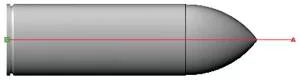
A variable radius formation is created along a vector (rotation symmetrically lying cylinder with variable radius), whose crown runs in the vector direction.
 |
|
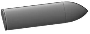
| Run: | Shape of the run of a vector. The run is set in the input Surface relief run. |
| Basic height: | Offset in Z direction to raise or lower. Alternative to manual numerical input the Z value can, following or , be adopted from the existing relief in the numerical input. |
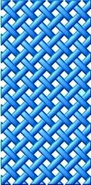
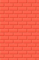
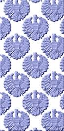
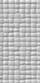
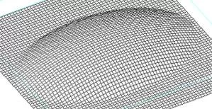
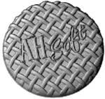
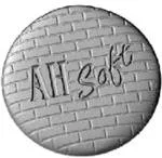
Create relief pattern (lattice, wall, sand, ..).
 |
|
| Lattice:
|
Creation of a lattice design within contours. Lattice data: for most applications the proposed settings for relief creation are recommended : ends = not rounded-off, basic height = thickness.
|
||||||||||||||||||||||||||||||||||||
| Wall:
|
Creation of a wall pattern within contours.
|
||||||||||||||||||||||||||||||||||||
| Pattern in contour:
|
Arrange relief pattern within contours.
|
||||||||||||||||||||||||||||||||||||
| Hammer effect:
|
Creation of a surface with hammered effect. The hammer blows are created through elliptical shapes, which vary through random numbers.
|
||||||||||||||||||||||||||||||||||||
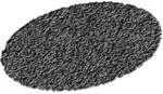
| Sand:
|
Creation of a random surface within one or several contours.
|
||||||||||||||||||||||||||||||||||||
| Pattern along line:
|
Arrange a pattern along a line (section).
|
||||||||||||||||||||||||||||||||||||
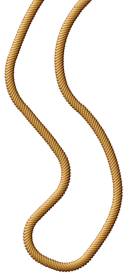
| Cord:
|
Rope (cord) creation along a section. The section may contain no kinks or tight curves! Double lines produce relief errors and should be avoided.
|
||||||||||||||||||||||||||||||||||||
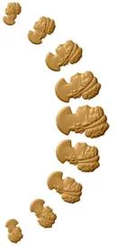
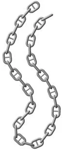
| Chain:
|
Creation of chains along specified sections and contours. The chain is created alternately with a lying and a standing link. Optionally, the chain can be created with a middle connection.
|